Choosing a CAD programme and creating the first prints.
I must admit that I was a little rusty when it came to 3D design. I last used MiniCAD in the mid-1990s and SketchUp around ten years ago.
I opted for FreeCAD, an open-source programme available for Windows, macOS and Linux. Armed with a calliper, I designed a replacement wheel for an old Lima toy train that my son had bought for one euro at the Sunday market, as well as supports for the top drawer of the dishwasher and a small hip joint pin for a Grendizer model that Father Christmas had given to my son.
The printer arrived in mid-April. The train wheel and dishwasher support turned out perfectly on the first print, but I had to make a few adjustments to the small pin.
The origins and evolution of the project
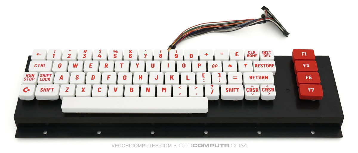
After familiarising myself with the basics of FreeCAD, I started working on a project I had been thinking about for some time: creating custom keycaps for my Commodore 64 with Gideon’s Ultimate board.
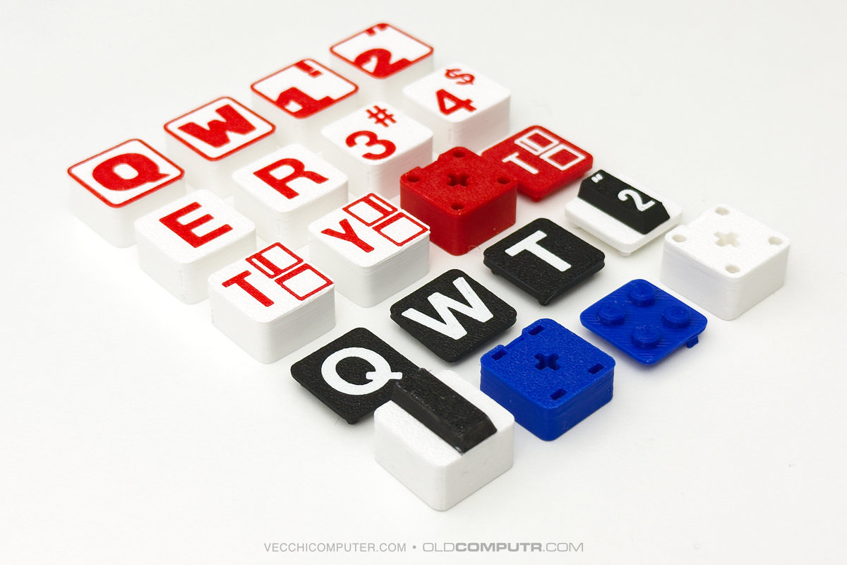
The following are all the iterations that led me to the final version of the keycaps. I started with the idea of typewriter-style ones, but then abandoned this in favour of island-style keycaps, as found on most modern keyboards.
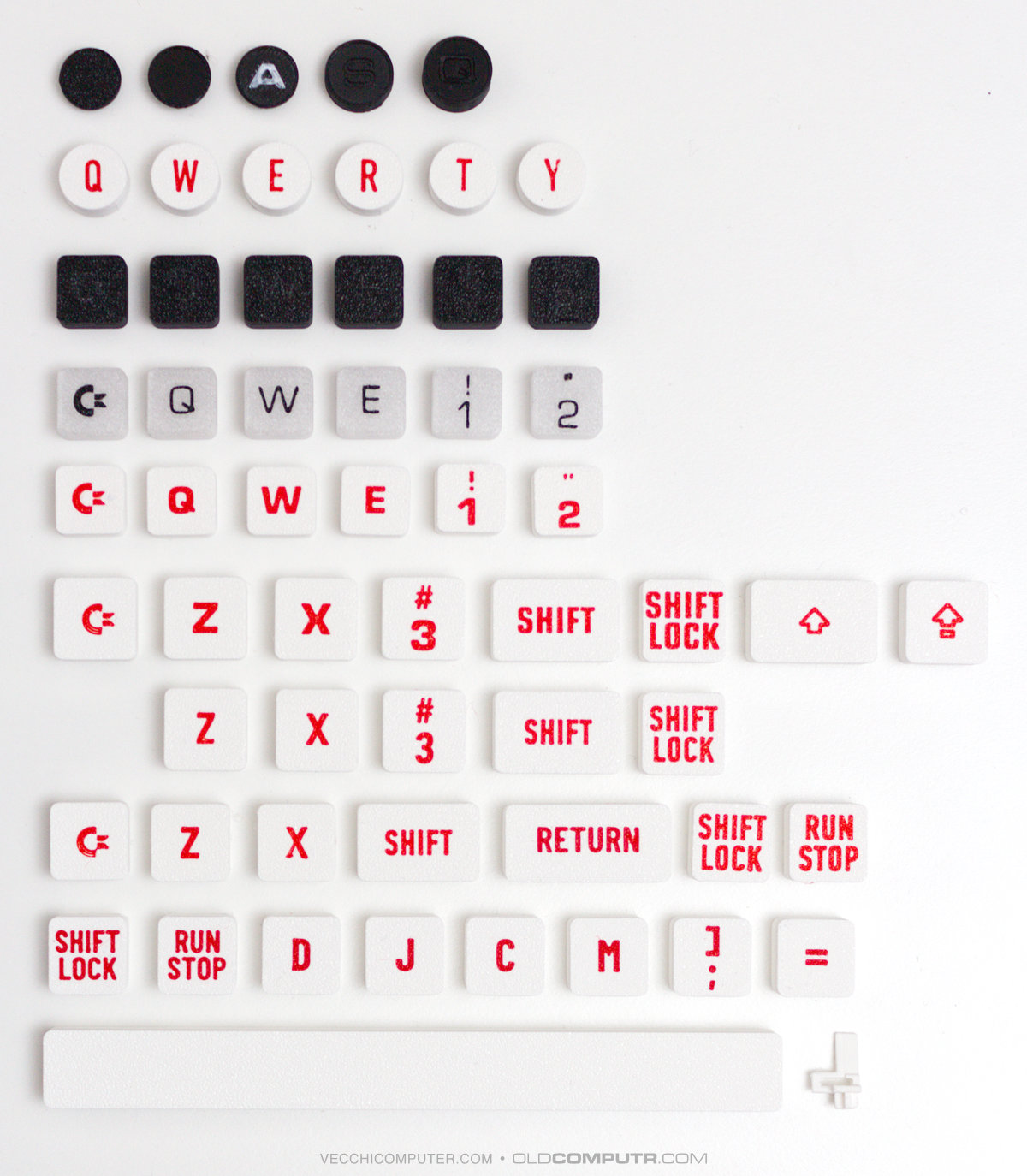
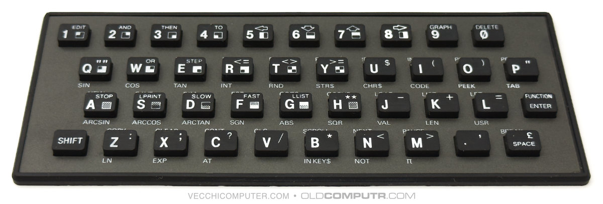
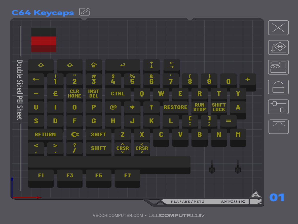
The idea of typewriter-style keys was appealing in theory, but the presence of the spring meant I had to design a cylindrical shape; after putting a few keys in place, I wasn’t happy with the result. I therefore switched to a more traditional rounded-square shape, starting with a size of 15x15mm; however, there was too much space between the keys. The base of the original keys is 18x18mm, so I tried printing some at this size. The original keys have a trapezoidal cross-section, leaving a comfortable gap at the top between them; extruding the 18mm across the full height, however, meant they were too close together. I removed 1mm from each side, ending up with a final size of 17x17mm and a height of 8mm.
There are several physical versions of the Commodore 64 keyboard; this design is suitable for the most common one. Since the island-style keys are coplanar and all the same height, it is not necessary to take into account the fact that, on the original keyboard, each row of keys has a different profile. Consequently, there are four distinct dimensions.
- The square used for most keys;
- The rectangle used for SHIFT, CTRL, RESTORE and the function keys;
- The rectangle for the RETURN key;
- The space bar.
Modelling in FreeCAD
I designed the 3D models using parametric modelling. In short, this means that I defined certain variables in the CAD file, such as keyWidth, and assigned them an initial value. When I drew the square representing the key, I specified that its width should equal the value contained in the keyWidth variable. Consequently, I could experiment with different dimensions and heights by simply changing the value of a few variables, and the model updated automatically. To prepare the four variants of the outer shell for each type of key, I only needed to adjust the width value.
Overall, I created four distinct models for the outer shells and one for the cross-shaped hook bracket, which appears once, twice or three times for each key. I then assembled each key variant in FreeCAD by positioning the shell and brackets and adding the reinforcements in the correct places. Finally, I exported the assembled model as an STL file.
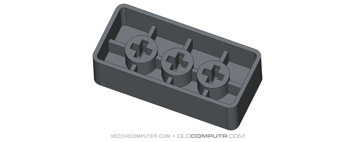
One peculiarity of the cross-shaped fitting, which I only noticed whilst measuring it with a calliper, is that on each side of the cross there is a small bulge, which corresponds to a notch in the keycap hole. It is this that produces the ‘click’ when the key is inserted and keeps it firmly in place. The key fit perfectly on the first print.
Problem 1: It is impossible to handle complex text in the slicer.
The first issue I came across was the poor handling of text in AnycubicSlicerNext – a problem also present in OrcaSlicer, from which it is derived. The same thing always happened: I would add a text modifier to the key model to “draw” the text in a second colour, assign a depth and enable on surface. It seemed to work correctly, even in the preview. I would then duplicate the key to prepare the next one. However, when I reopened the saved project, the modifier’s thickness would revert to 0, on surface would be disabled, and the text coordinates would often change. Alternatively, they would change as soon as I double-clicked to restore the text’s depth.
The thickness reverting to 0 is definitely a bug. I think I’ve figured out why the coordinates were changing, though: as soon as you enter text, the coordinates refer to a generic box. However, when you define the content and close the dialogue box, the application recalculates the coordinates based on the actual footprint of the character’s graphic outline. Not only is keeping all the keys consistent an unsolvable problem, it is also an unmanageable manual task in the slicer, especially for keys with a number and a symbol or two symbols. While the text tool is fine for simple engraved, coloured or raised lettering on a model, it lacks the precision required for a project like the one I was working on.
Furthermore, managing fonts in the slicer is rather cumbersome: Barlow Condensed has 18 variants – thin, thin italic, light, light italic, medium, regular, and so on – but the slicer simply displays “Barlow Condensed” along with the bold and italic icons. To select a different variant, you need to open the Advanced section and try all the options in the Collection menu – shown as mere numbers – until you find the one you want.
The solution to these text-related issues was to use an SVG file for each key. This gave me complete control over the positioning of each glyph, and SVG modifiers do not suffer from the issue of zero thickness.
Creating SVG files
Using the Affinity suite (now owned by Canva and completely free), I created a separate layer for each keycap. Exporting to SVG also presented a few unexpected issues, so I’m sharing my experience and what I’ve learnt to save time for anyone looking to develop a similar project or create SVGs that need to match the actual dimensions of a 3D model.
- The SVG format in Affinity does not export the absolute dimensions of the drawing: the viewbox is simply set to 100%, so you need to disable the ‘Set viewbox’ option when exporting. From what I’ve read online, Inkscape may be able to save the absolute dimensions of the drawing with width and height in mm.
- Although the SVG file is essentially vector-based, the dimensions are set in pixels. To obtain the actual dimensions in mm, the slicer imports the file at a resolution of 96 dpi: to ensure the dimensions in Affinity match those in the slicer, this resolution must also be set in the Affinity document (Document › Setup › Document Setup).
- You must enable the Export text as curves option to convert the text to a path during export.
- At 96 dpi, the curves on a 17mm document appear too rough, so you need to set the document resolution to a multiple of 96, and scale the SVG file in the slicer. Example: double the document resolution (96 x 2 = 192 dpi), and halve it in the slicer (import the SVG and scale it to 50%).
- In order to have complete control over the positioning of the SVG on the model, the dimensions of its contents must match the dimensions of the model exactly. In my case, I placed four small triangles at the corners of a 17×17 mm square. As the triangles are outside the button, they do not affect the print.

- For some of the more “creative” key designs, where part of the glyph extended beyond the 17×17 square, I had to convert the text to a path before exporting the file, and remove the part of the polygon extending beyond the edges. Otherwise, it wasn’t possible to centre it correctly in the slicer. In short, the entire content of each key must fit within the 17×17 square.
Furthermore, whilst working on some keys with symbols, I had to change the font or size of certain glyphs to make them more uniform, just as was done on the original keyboard. If you look at the original keyboard, the quotation marks have been enlarged, the asterisk is probably a separate design that does not belong to the font, and the brackets have been reduced in size, meaning they are not the same size as the letters and numbers: in practice, these glyphs are either visually uniform in size or adapted to the limited space available. I have tried to avoid overly unbalanced variations; for example, I have not altered the size of the double or single quotation marks, but I have slightly reduced the size of the dollar sign because otherwise the vertical lines would have protruded too much; I had to choose a different font for the square brackets, which were too large and thin; the +, – and * symbols have been centred and enlarged, bringing their thickness into line with that of the letters.
Problem 2: the key stems are not all the same.
I realised far too late that, in true Commodore tradition, not all the key stems are the same. On this keyboard, six random keys plus SHIFT LOCK and RUN/STOP have a taller cross. The original keys have a much deeper recess for the cross on the stem, so this difference is irrelevant. However, as I wanted to create a keyboard that was as ‘low profile’ as possible, I had unwittingly measured one of the short stems and based the height of the cross-shaped hole on this measurement. When I positioned all the keys, some were over 1 mm higher – what a nuisance!
To avoid reprinting all the keys, I only reprinted the eight problematic ones, carving out a 1.4 mm recess in the top of the shell. However, this left only 0.6 mm above the hole, which was slightly too little. In the final version, I increased the height of the key by 1.5 mm, bringing it up to 9.5 mm from the initial 8 mm.
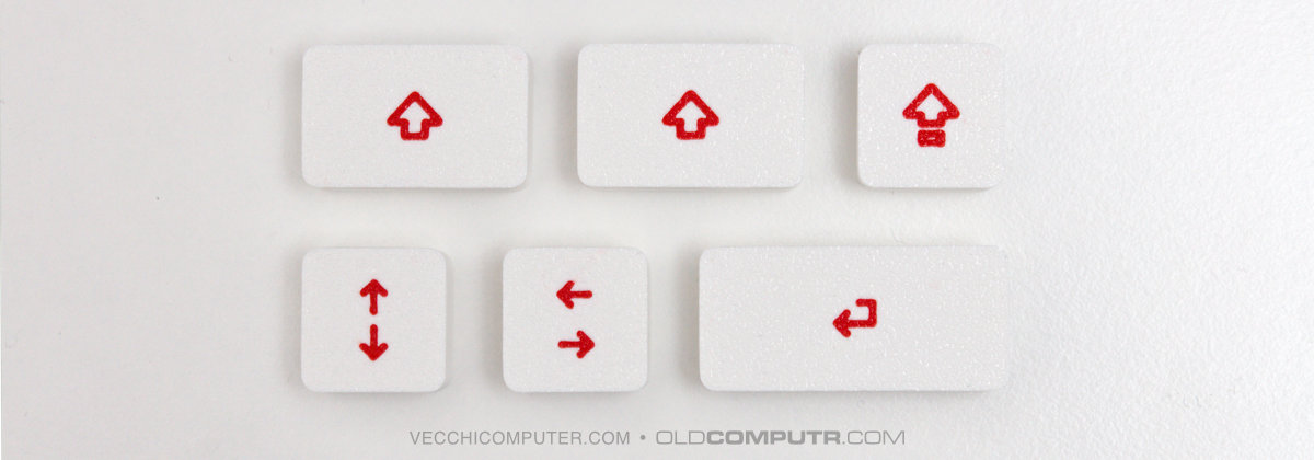
For an even more modern look, I have also prepared alternative versions of the Shift, Shift Lock, Return and Cursor keys.
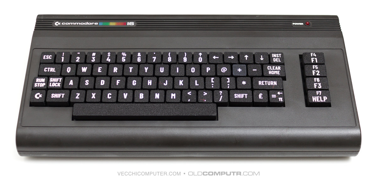
The final result
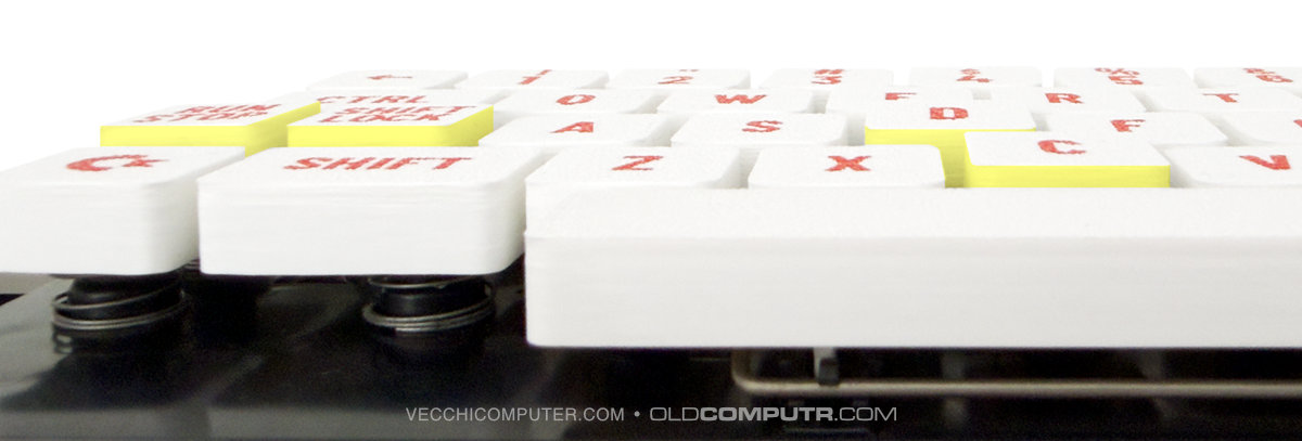
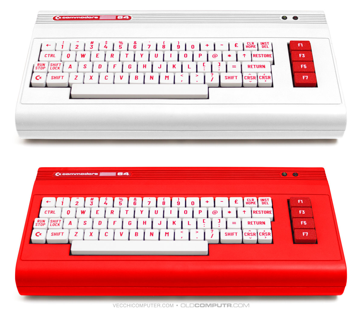
Here is the keyboard with all the keys. The first two PLA+ filaments I ordered came in red (for the train wheel) and “milky white”. I printed the function keys with the colours reversed.
I quickly designed a label as the original one is missing from the case I’m using. I’d like to paint the case, so I’ve done a couple of tests changing the colour in Affinity. I think white is my favourite.
The keys can, of course, also be used on a VIC 20, provided it has the same keyboard model.
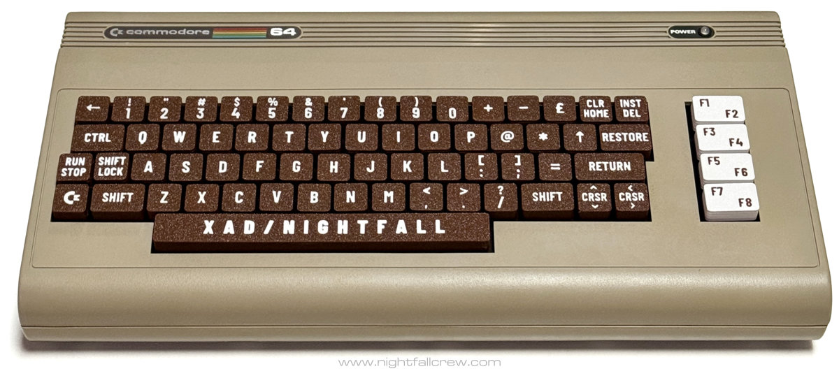
At the request of my dear friend Davide (Xad of Nightfall), who has followed the project from my initial tests to the final printing of a complete set, I have created several variations of the function keys. Here is a photo of one of his Commodore 64s with a brown-and-white keyboard. This is the link to the article on his blog.
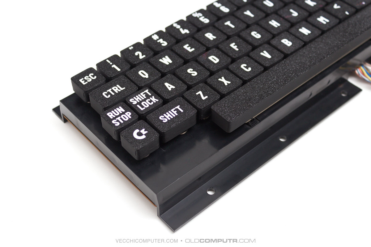
Once the project was complete, I also prepared the glyphs for the few missing keys on the Commodore 16, given that its keyboard layout is similar to those of the 64 and the VIC 20. Then I printed a set in black with white graphics.
PETSCII, variations, and future developments
There are several reasons why I didn’t include the PETSCII symbols: I wanted a keyboard with a modern look; the symbols would be too small for 3D printing; and, in practice, I never use them. Then, actually, I did a couple of tests, and when placed next to the letter, they don’t end up being that small after all… with a bit of patience, I could draw all the symbols in vector format, as I haven’t found anything ready-made online. The fact remains that to print the graphic symbols, the printer needs to be multi-colour and have good precision. Davide me to enjoy the precision of my printer while it’s new, because it will deteriorate over time…
After preparing all the “normal” keys using a font that roughly resembles the originals, I tried out some more extreme, artistic or graphic variations – I’m not sure how to describe them. I’ll take my time drawing all the keys and see the overall effect, which is hard to judge by looking at a single key. In the meantime, I’ve ordered some more PLA filament in black, blue and yellow.
I’ve also tried designing a modular key, with a fixed base and a removable top section, with the aim of not putting too much strain on the original Commodore 64 key stems. However, I haven’t yet come up with a practical and functional solution. If the hooks are too small, they break; or too much precision is required for 3D printing, and sometimes they fit well, other times they struggle, depending on the colour I use; if I lower the tolerances, the top part comes off too easily. In short, I either need to work on it some more or accept that it isn’t a viable solution.
One idea that I’d like to finalise – the bulk of which is complete, as you can see in the photo – is the “musical” key. This would involve adding the black piano keys to the 64’s keyboard, with the same layout as the overlays sold in the 1980s. They might be of no use to anyone, except perhaps a handful of people who make music with the Commodore 64. But they’re nice.
I also tried printing the top part of the key to be compatible with Lego. Apart from the obvious pointlessness, it forces you to print each key with supports, regardless of the model’s position on the build plate. For now, the idea has been scrapped.
Being able to design a 3D object and print it at home is a fantastic idea. Perhaps I should have thought of it sooner, but I’m glad I started with more mature, less experimental technology at an affordable price.
I completed the project in my spare time, within a week of the printer arriving, learning the basic functions of the slicer as well as picking up some extra knowledge about FreeCAD. Perhaps some of the issues I’ve mentioned are familiar to more experienced makers, but I’ve dealt with them, or rather, I’m dealing with them as I go along.
Download
You can download the STL files for the keys, the 3MF file with all the glyphs in place and the SVG files for creating custom keys from Printables.
]]>